State Machine Diagrams
State machine diagrams model the dynamic behavior of a system by showing how objects change state in response to events. They are particularly useful for modeling reactive systems, user interfaces, and protocol specifications.
Palette
The palette contains elements for creating your state machine diagram:
State (empty)
State with Body
State with Body and Fallback Body
Initial State Node
Final State Node
Code Block
Transitions are created by connecting states directly on the canvas (they are not palette elements).
Getting Started
States
To add a state:
Drag and drop the state element from the left panel.
Double-click the shape to edit properties.
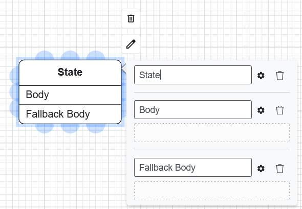
Name: The name of the state.
Body: Define the behavior (actions) of the state.
Fallback Body: An optional action executed if the state is entered without a specific trigger.
Transitions
To create a transition:
Click the source state.
Drag from a blue connection point to the target state.
Double-click the transition arrow to edit its Name and Parameters.

Initial and Final States
Every state machine should have an Initial State (the entry point) and optionally one or more Final States (termination points).
Drag the Initial State element from the palette. Connect it to the first meaningful state with a transition.
Drag a Final State element to indicate where the machine terminates.
Code Blocks
Code blocks allow you to define custom behavior within states using Python code. Drag a Code Block element onto the canvas and double-click to open the code editor.
The code receives a session parameter for accessing state machine context.
Code Generation
State machine diagrams do not support direct code generation. They are used as method implementations within Class Diagrams. To generate code that includes state machine behavior, generate from the Class Diagram that references the state machine.